Setting up Simplify3D to print planes
Important note about version 5 of Simplify3D:
Version 5.0.0 is not compatible with our models. Please update to version 5.0.1 or stay on version 4.1.2. In version 5.0.1 and later you need to set two following options in our factory files:
- Infill tab / Solid Infill Threshold Area = 0 mm^2
- Advanced tab / Slicing Region Repair Mode = Alternating Fill
Since we provide factory files for all parts, all of the necessary work, such as setting up processes and bed layout has been done for you. If you’re using original Prusa i3 compatible printer with direct drive extruder, all you have to do is open the factory file, hit Prepare to print button and save the resulting gcode to your printer SD card (or just use our prepared gcodes, made precisely this way).
If your printer requires tweaking the settings, use the factory file as a starting point and adjust only the necessary parameters. Please note, any Simplify3D settings couldn’t fix a poorly built or designed printer. Check all the axes could move freely and are perfectly perpendicular to each other. Also, keep your hotend in a good shape, and if you’re still unable to tune up the extrusion, consider upgrading it. Direct drive E3D V6 hotend seems to be a perfect choice.
Further in this article, we’ll try to explain the aspects of preparing the gcodes from scratch, so you better understand all the settings.
Let’s start with configuring the basic process for the wing/fuselage part.
Extruder
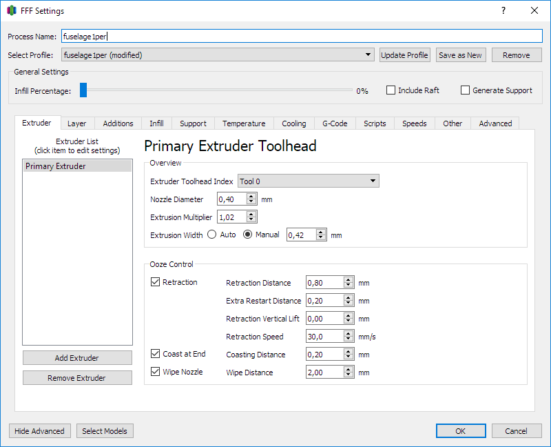
Set the values according to the image as a starting point. This tab contains all the necessary settings to tune up the extrusion and retractions.
Please measure the average filament diameter of each spool with callipers prior to altering these settings, we’ll address this later on the “Other” tab. 1,75 mm and 3 mm are just the systems, and the actual diameter value may vary a bit causing under extrusion or over extrusion.
The Extrusion multiplier is a value where you can adjust the overall weight of printed parts. We need to make the part lightweight yet strong enough. You can find suggested weights of most parts in the PDF user guides of each plane. Print the test part (the bigger the better), check the weight and compare the resulting weight to the diagram. The tolerance should be within a few grams. Calculate the extrusion multiplier as a difference between resulting and suggested weights.
The Extruder tab also contains all the necessary Ooze control settings. For direct-drive extruders (hobbed bolt right above the hotend, the stepper motor is part of the X carriage) the Retraction distance value should be about 0,8 – 1,5 mm. For Bowden extruders (extruder stepper is not part of the print head and the filament is being fed through a long Bowden) the Retraction distance should be in between 4 – 8 mm. In general, if you experience stringing, raise the Retraction distance in steps of 0,2 mm until the stringing stops. Setting the retraction distance too high could result in clogged hotend. If you experience under extrusion after travel move of the head, there is Extra restart distance to prime the nozzle before starting a print move. These values require some tweaking, but once you find the right settings, you just use the same values for any factory file in the future.
If you’re going to print from foaming material, such as LW-PLA, set the Extrusion multiplier around 0,5 and set the Retraction Distance to 0. Turn off the Coasting and Wiping as they have little to no effect, but keep the Extra Restart Distance to compensate oozing.
Layer
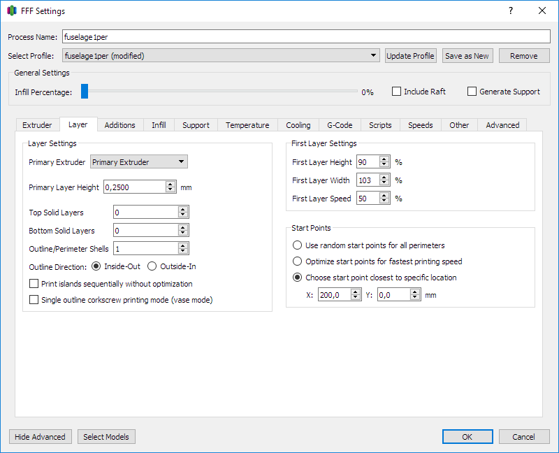
Set the values according to the image for a general single wall part. This tab contains all the settings determining the number of perimeters, layer starting point – seam and possibly number of bottom/top layers if necessary (control surfaces horns, steep overhangs, Pawnee’s face, etc…). The layer height is usually set to 0,25 mm for the best speed/quality ratio. If you experience layer start under extrusion, setting the layer height to 0,2 mm slows down the extrusion and helps to correct this.
We’re using 2 perimeter setting for first few millimetres of print to improve heatbed adhesion and reinforce the bottom part to fight warping caused by heatbed temperature. Use Variable settings wizard to split the process (see below).
Start Points determines, where the layer start seam is positioned. Setting the start point to optimized or random position results in zits spread all over the print. We could control where the seam is located by setting it to the fixed value and rotating the parts on the bed accordingly. We’re usually trying to put the seam on the edge or to the very bottom of the fuselage where no edge is available.
You can also adjust first layer parameters here if you’re experiencing bed adhesion issues, but remember, the key is nicely squished first layer and proper heatbed preparation according to the surface of your bed. Always degrease the surface. For glass bed, use ultra-strong hairspray and use a razor blade to scratch the surface to look like frosted. The PEI sheet usually doesn’t need any extra treatment, but sometimes slight sanding with fine-grit sandpaper and degreasing the suface helps. PVA glue sticks usually can’t hold the part with higher bed temperature, we’re using to prevent edge and corner lifting.
For models that are designed to be printed in a vase mode, tick the Single outline corkscrew printing mode option.
Additions
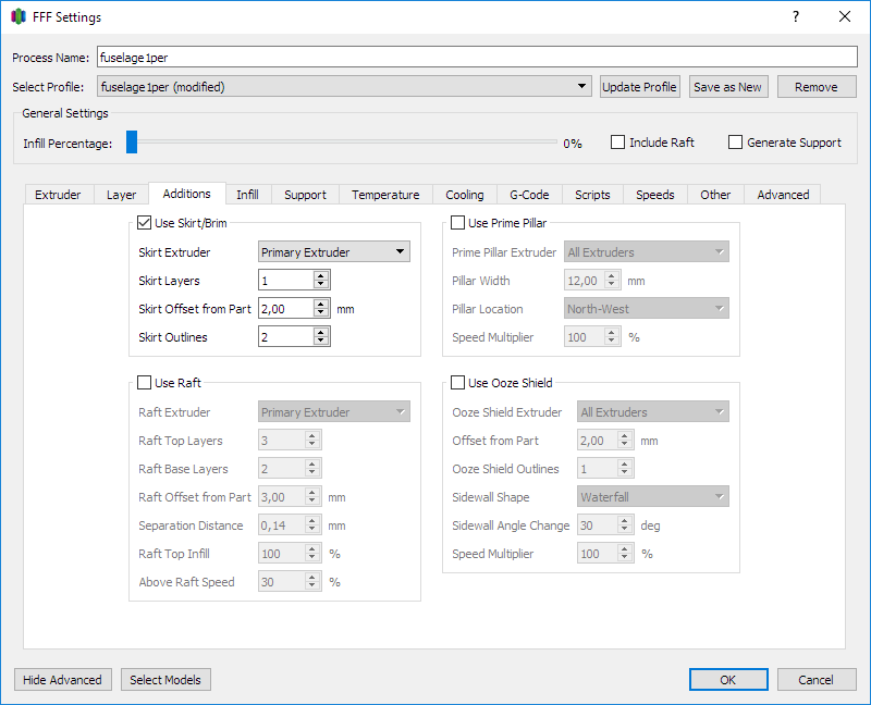
The Additions window lets you set the Skirt or Brim. The skirt is necessary to prime the nozzle before printing the actual part. 1 outline is usually enough, use more outlines for smaller parts. If you experience poor heatbed adhesion (lifting trailing edges, etc…), you can set the Brim in this tab. Use the following values (thanks Alex T):
- Skirt layers: 2
- Skirt offset from part: 0,30 mm
- Skirt outlines: 9
This creates additional support, improving the heatbed adhesion, yet easy to remove after the print has been finished.
Other features from this tab are not necessary for us to change.
Infill
The infill tab is very easy to set. We’re usually using 0% infill for our planes. If the infill is necessary for certain parts (f.e. Stearman landing gear, etc… ), consult the stock factory files, where the corresponding infill is already set for you.
Support
The same as for infill pays for supports. We usually don’t need the supports, but for a few parts like spinners, etc. See the corresponding factory files for more details.
Temperature
The temperature of hotend is very important for the strength of your parts. In thin wall printing, we need to print as hot as possible for proper layer bonding. As a good starting point use value of 230°C for most PLA brands.
To determine the right temperature for your printer and filament, you can print a temperature tower. You can print a test file and set the temperature changes for every 20 layers. That will change the temperature every 1 cm of Z height.
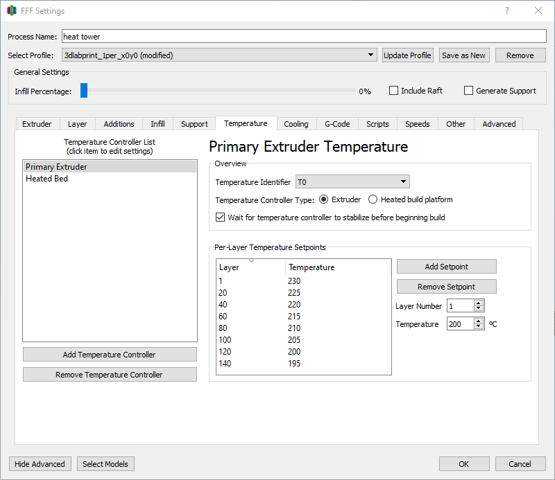
Examine the print and find the best strength/quality ratio.
You can also use our preconfigured Heattower factory file. There are two small single wall columns on the bed distant from each other to find also the right retraction settings.
As for the heatbed, the temperature of 60°C seems to be optimal for the best first layer adhesion. The part pops off the heatbed when the temperature drops bellow 40°C.
Cooling
Turn the cooling fan off for thin wall printing! The part is able to cool down easily on its own and the cooling fan compromises the overall strength of the print. You can possibly use the cooling fan only for thick parts like motor mounts, but usually this is not necessary as well.
G-Code
Adjust these values only if your printer has different heatbed dimensions or needs some specific options. Usually, it’s not needed to change anything here. Even if you have a larger bed, you don’t need to set the correct dimensions, as these are within limits of your printer bed and printing more parts at once increase the risk of failure.
Wanhao D6 seems to have some “printing out of the bed” issues, this is the place where to fix this probably.
Scripts
You can add some custom starting and ending scripts here according to your needs.
The basic start script contains only homing command G28
Example of more complex starting script:
M201 X1000 Y1000 E600 ;set accelerations in mm/s/s
M92 E161.3 ;set E-steps value
G28 ;home all axes
G92 E0.0 ;reset the extruder position
G1 X1.0 F2000 ;prime the extruder and clean any ooze
G1 Y60.0 E4.0 F1000.0
G1 Y100.0 E8.5 F1000.0
G92 E0.0 ;reset the extruder position again after priming
Set export file format for XYZ daVinci printers here as well if required.
If you have a Prusa MMU2 upgrade, you need to add a starting script to load the filament or manually load the filament prior to starting the gcode.
Speeds
The default printing speed we’re using is 60 mm/s, outer outlines are at 70%. Since we’re printing with rather high hotend temperature, the plastic tends to ooze from the nozzle. Setting the retractions in extruder tab and as fast as possible travel moves are very necessary to prevent stringing. Use values of at least 130 mm/s for travel moves. If your hotend can’t handle the temperature, slow down the print moves to ensure proper layer bonding.
Also, don’t forget to set speeds overrides for layers below 15 s.
Other
The other tab contains one very important value. It’s the Filament diameter. Measure the actual diameter of filament on a few spots of every spool and insert the average value of your measurement here. This allows for compensating extrusion for various spools.
All the other values may remain untouched.
Advanced
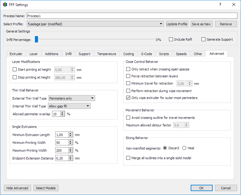
Set the values according to the picture.
Very important is Ooze Control Behavior, as we need retractions for all spots.
The Layer Modifications determines the Z-height interval, this process is effective for. This is being set with Variable settings wizard and is not usually needed to be set manually, but you could adjust the heights here if you need to.
Select models
In a Select models window, we’re able to choose for which models this particular process is being used. It’s useful if you want to print multiple parts at once with different settings.
Variable settings wizard
For setting different parameters in various Z-heights, use Variable Settings Wizard located in Tools menu. This allows splitting the process in specified locations and for adjusting the settings in each process separately.
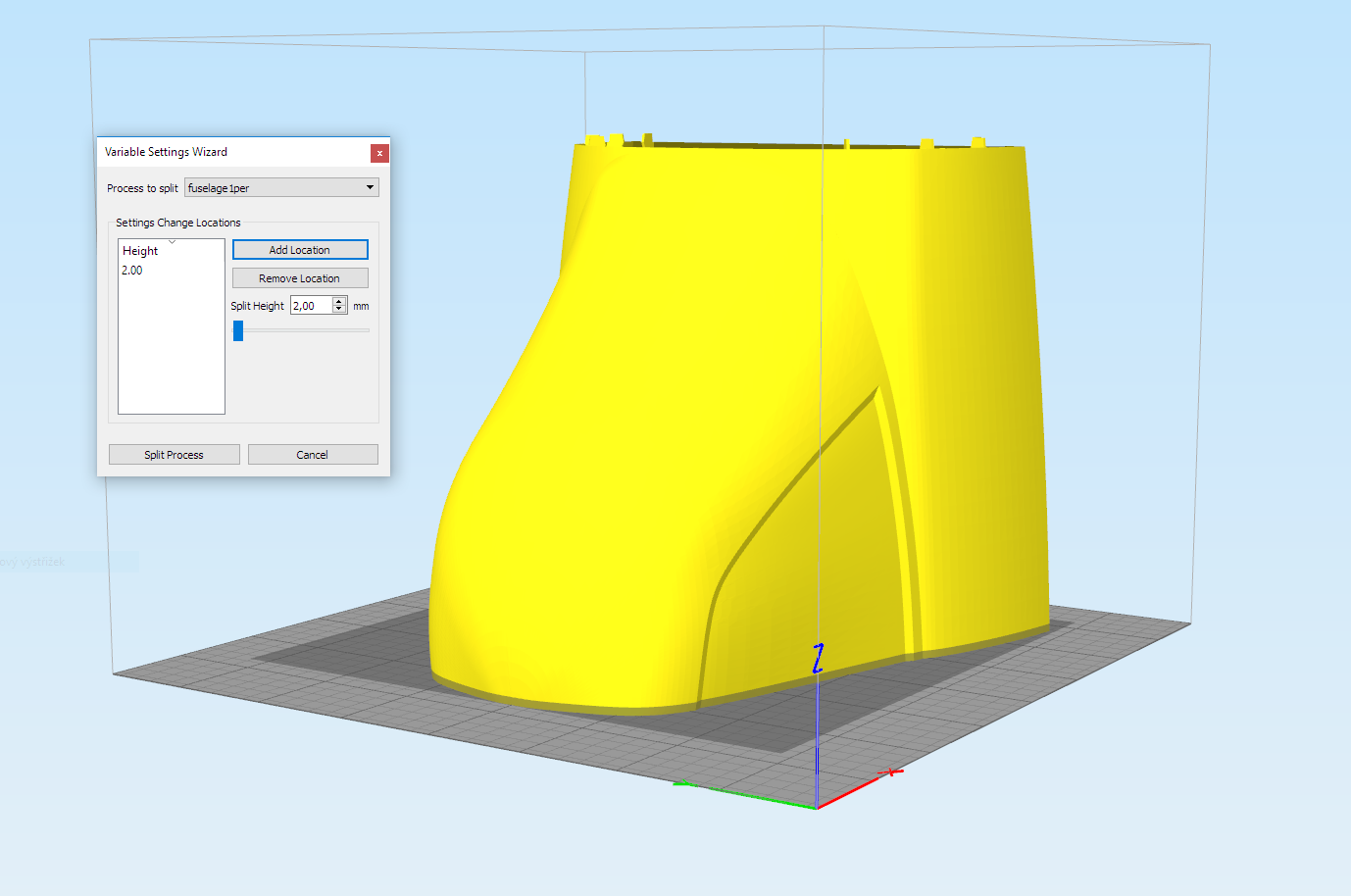
We’re usually using this feature to split the process in height of first few millimetres to add 2 perimeters settings, but it could be used to set some other parameters in different heights as well. For example, reinforcing the Landing gear slots for Zivko Edge.
Slicing
Once your process is configured, first hit the Prepare to print button, after that select all the processes. Sometimes some process may overlap the other. This is usually intentional for some parts. After slicing check the resulting visualisation for correct placement of layer start seam (retraction line), correct speeds, and see if there are no unwanted gaps between layers.
Save the gcode to SD card and print it. You’re done!
A complete list of all Simplify3D process parameters can be found in this Simplify3D forum post.